Page Contents
Solid Edge 2020 Tutorial: Part Modeling in Synchronous Mode Exercise -5
Hello, today we are with our new Solid Edge tutorial for Synchronous Mode. This tutorial will show you how to make a sketch, a mirror in the sketch, a project sketch, extrude, cut, fillet, and synchronous edits. You may also do the same exercise by watching videos on YouTube. This exercise can help you improve your part modelling efficiency.
We learned how to use the extrude, cut, fillet, chamfer, and synchronous edit commands in our last Exercise. So, for this drill, I’ll repeat the same practice. However, I will proceed in a step-by-step manner, which will make practising easier. So, let’s get started…
Please click here to download the drawing file for Exercise -5.
Click here to Read Article for Exercise – 4. Also, you can watch it here.
Solid Edge Tutorial: Synchronous Mode
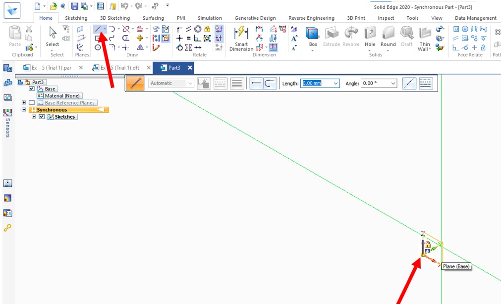
Step -1:
Select the line command and lock the plane by pressing the F3 key.
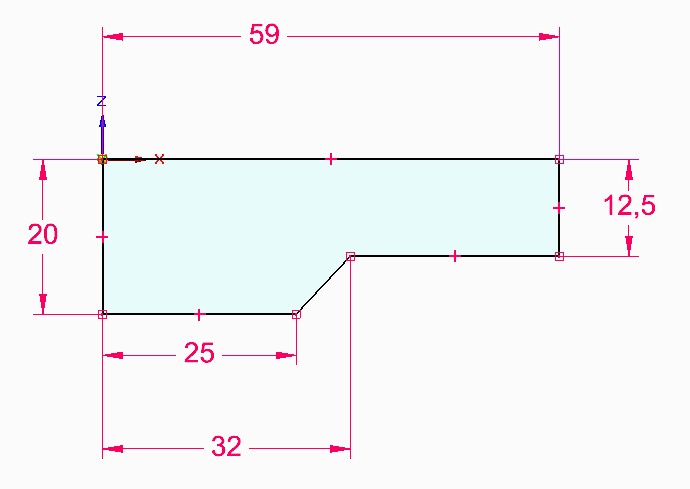
Step -2:
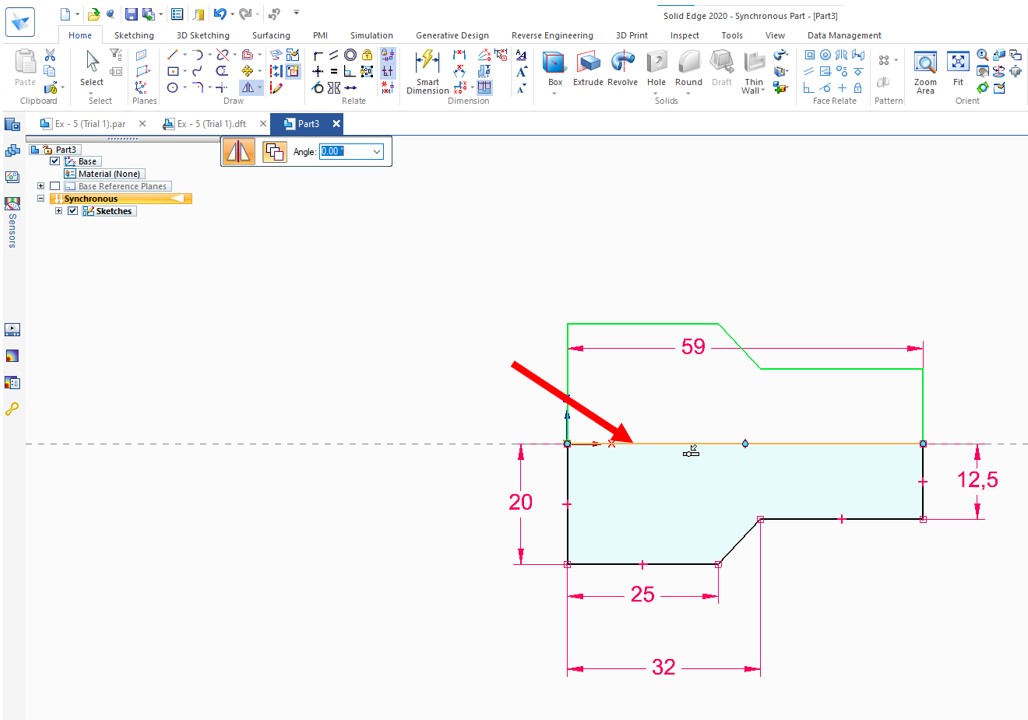
Create a sketch on XZ Plane below the X-Axis. As in the sketch and apply dimensions to make the sketch fully constraints.
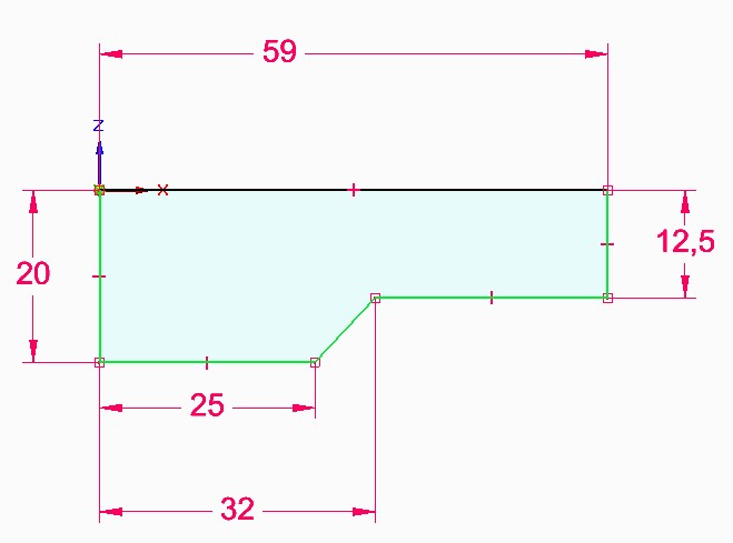
Step – 3:
Select the sketch entities for making a mirror profile with respect to the line in X-Axis.
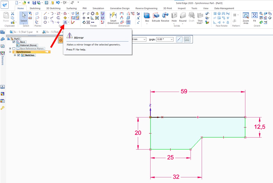
Step – 4:
Now, Click on the mirror command.
Step – 5:
Select a Marked horizontal line to create a mirror sketch. Then Right-click one time to OK.
Step – 6:
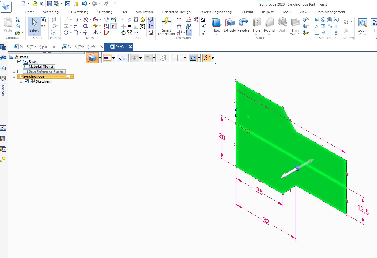
Select a complete profile.
Step – 7:
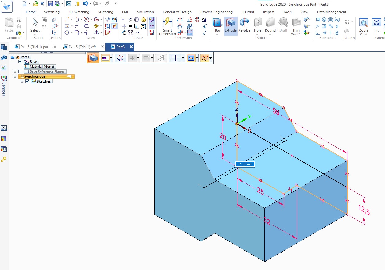
Pull the arrow up to 30 mm, press the Shift key to extrude symmetrically.
Step – 8:
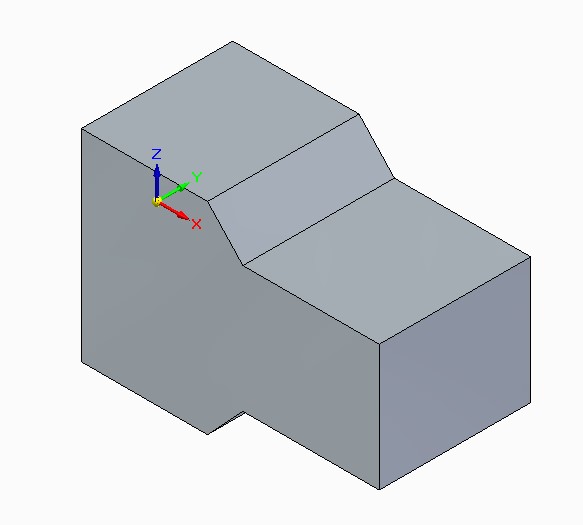
Now extruded profile is ready.
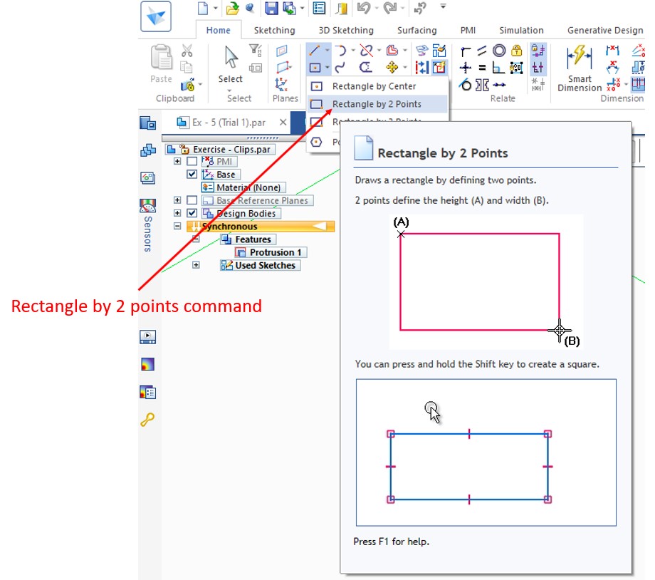
Step – 9:
Click on Rectangle by 2 points command.
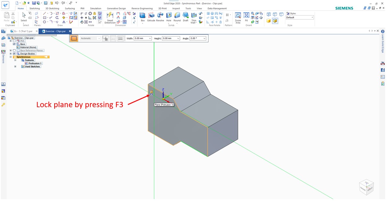
Step – 10:
By pressing the F3 key, lock the marked plane.
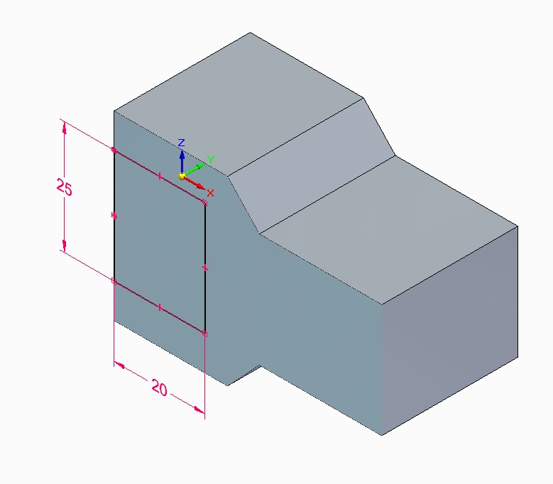
Step – 11:
Draw a rectangle according to the drawing like that.
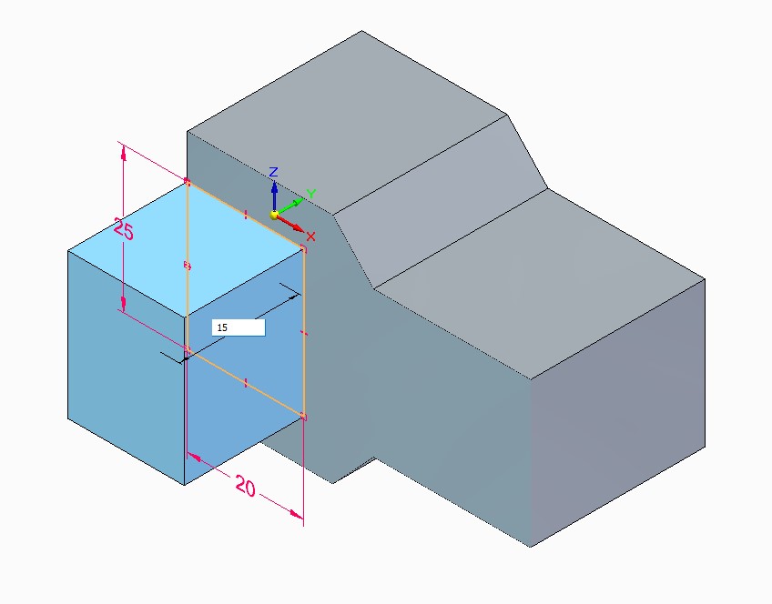
Step – 12:
Select the profile and extrude this up to 15 mm.
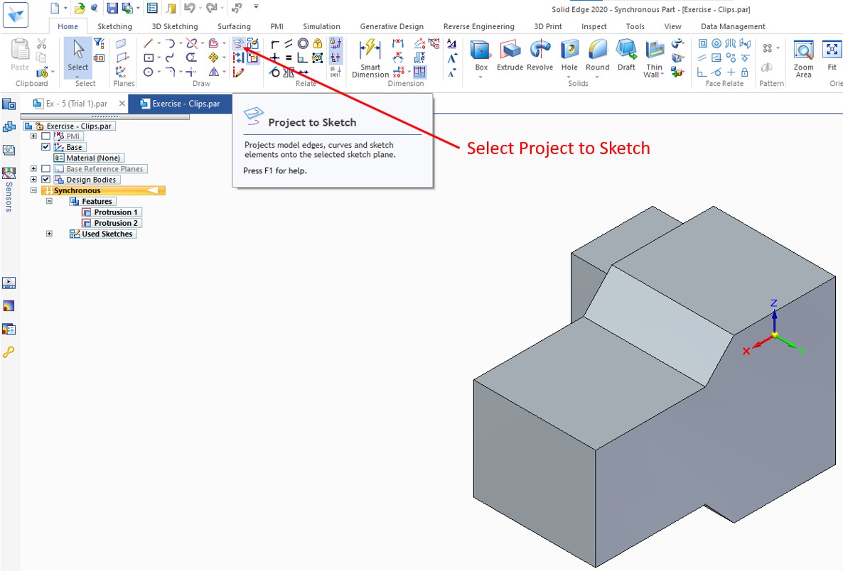
Step – 13:
Select Project to Sketch.
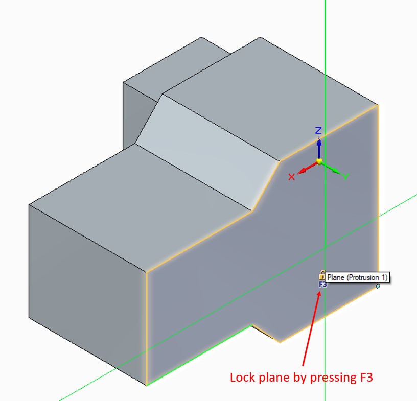
Step – 14:
By pressing the F3 key, lock the marked plane.
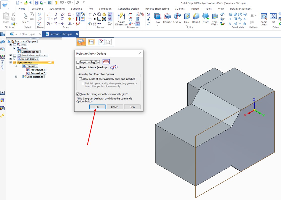
Step – 15:
After selecting the plane, the Pop-up will open. Just leave it unchanged and click Ok.
(Note – This pop-up may not appear if un-ticked “show this dialogue when the command begins”. In that case Step – 15 need to skip.)
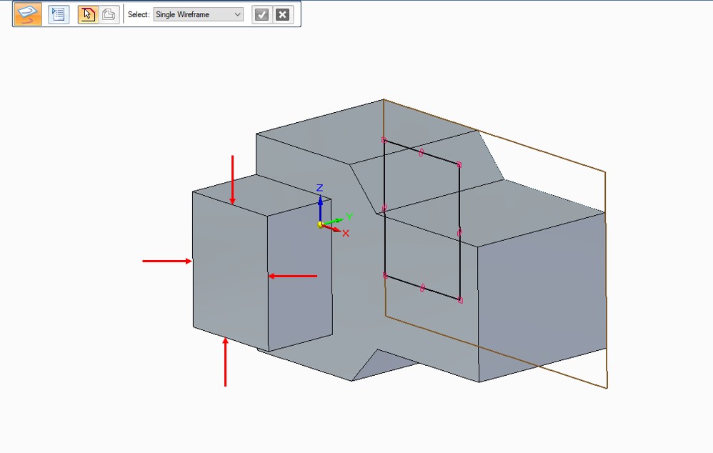
Step – 16:
After locking the plane, select the marked edges of the previous feature. Then press escapes to exit from project command.
Step – 17:
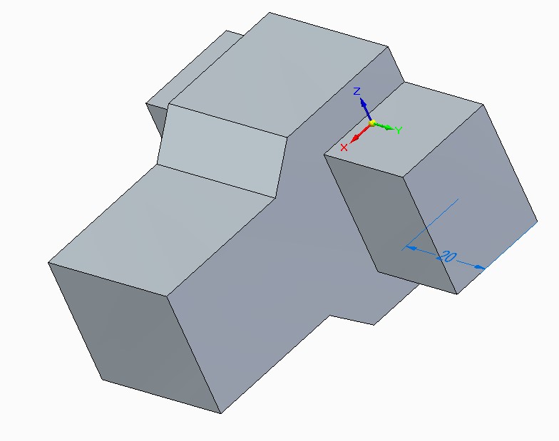
Select the profile and extrude it up to 20 mm.
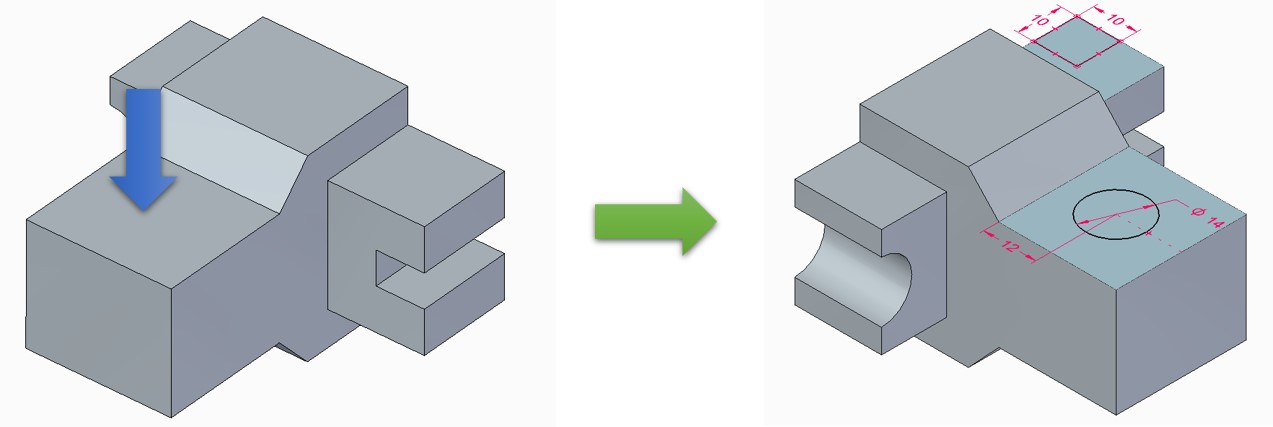
Step – 18:
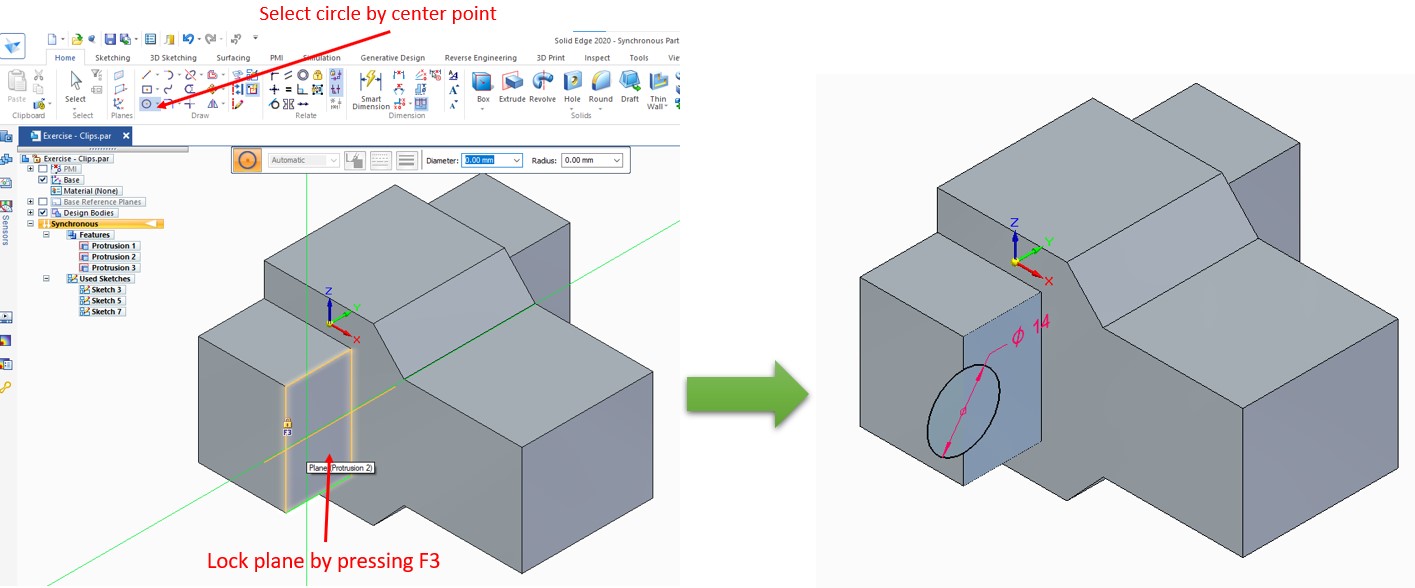
Select circle by a centre point, and lock the marked plane. On the middle point of the edge, draw a 7 mm radii circle.
Step – 19:
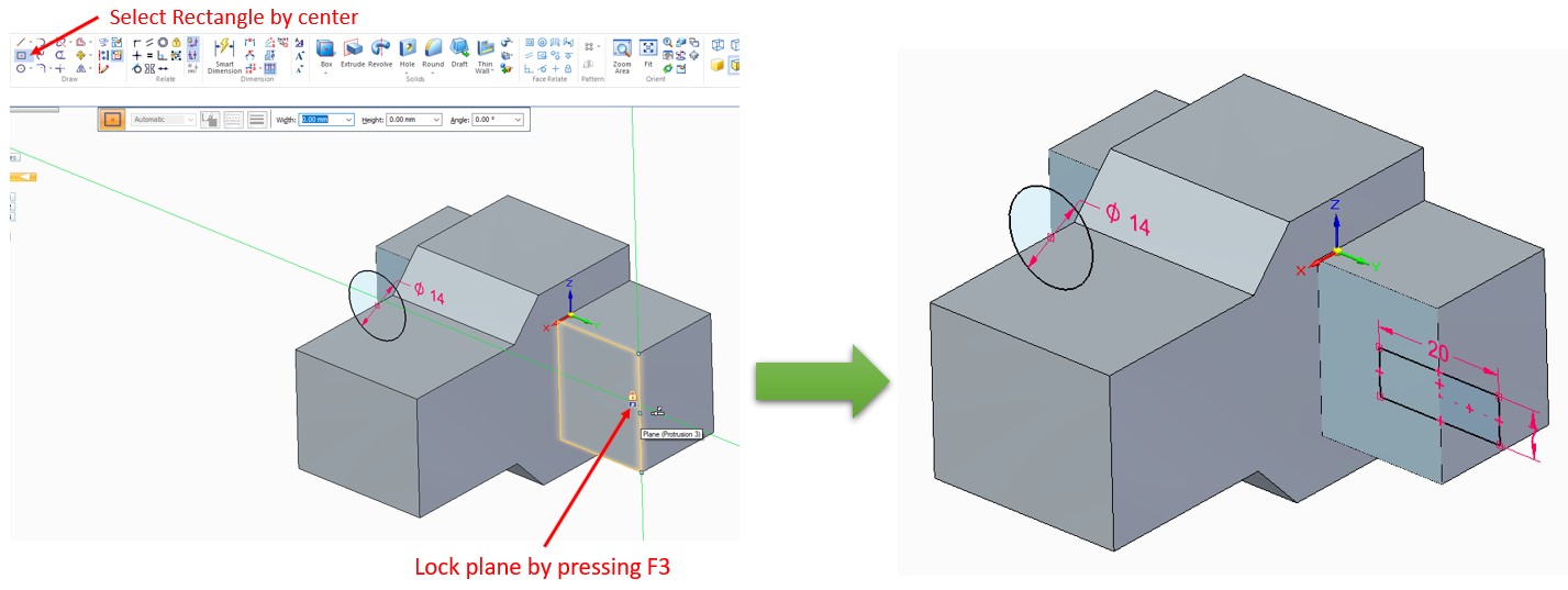
Now, Follow Step -18 for drawing a rectangle on another side face.
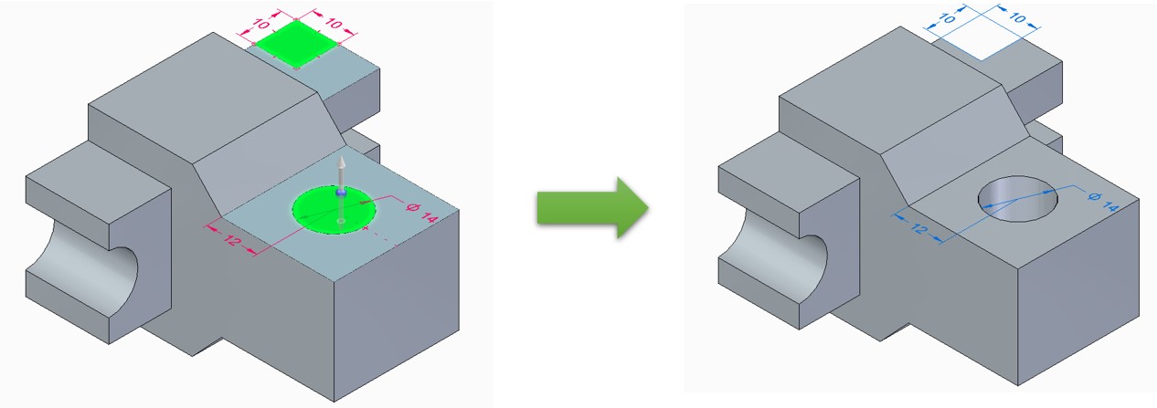
Step – 20:
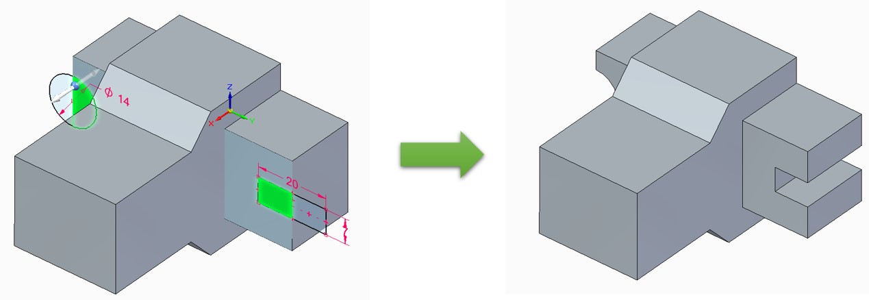
Select the profile, and create through the cut.
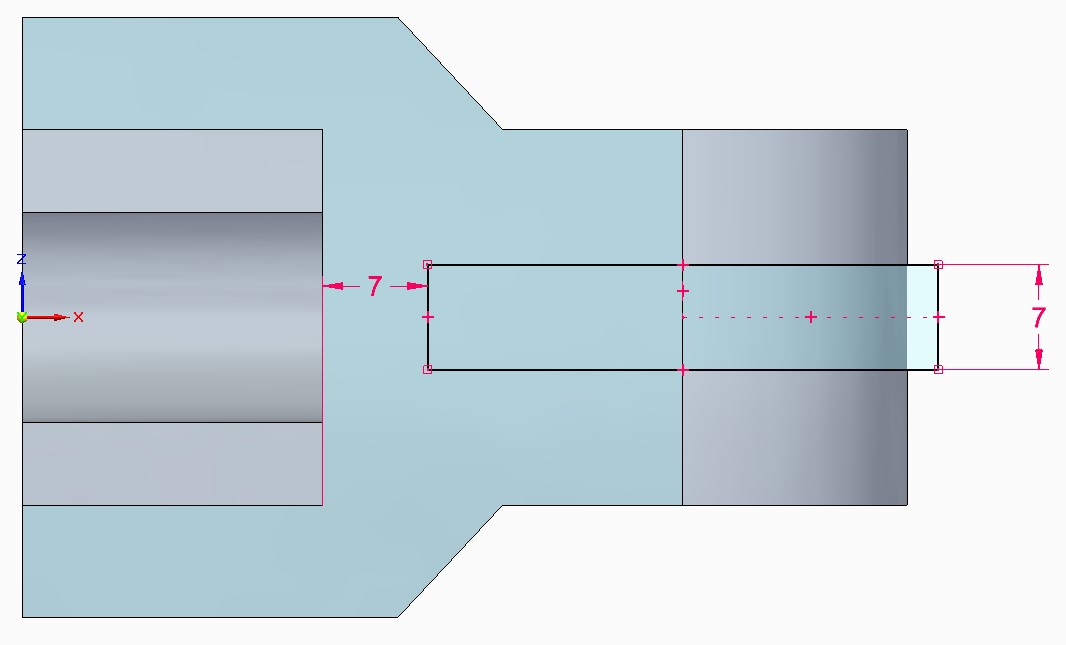
Step – 21:
Create a circle and rectangle according to the below image.
Step – 22:
Drag these profiles and create a thorough cutout.
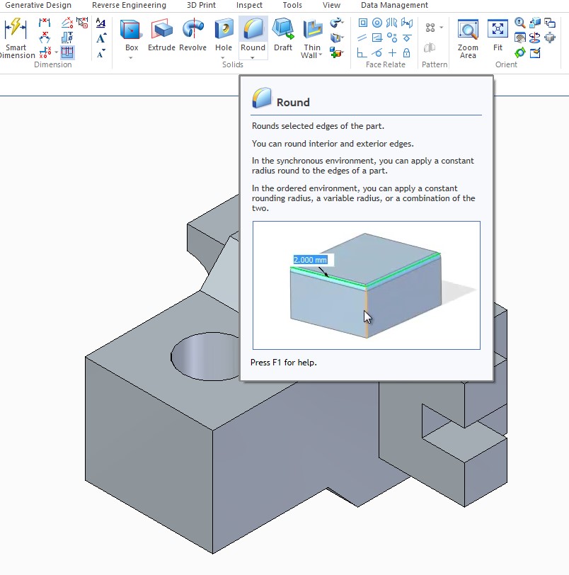
Step – 23:
Select Round Feature to apply fillets.
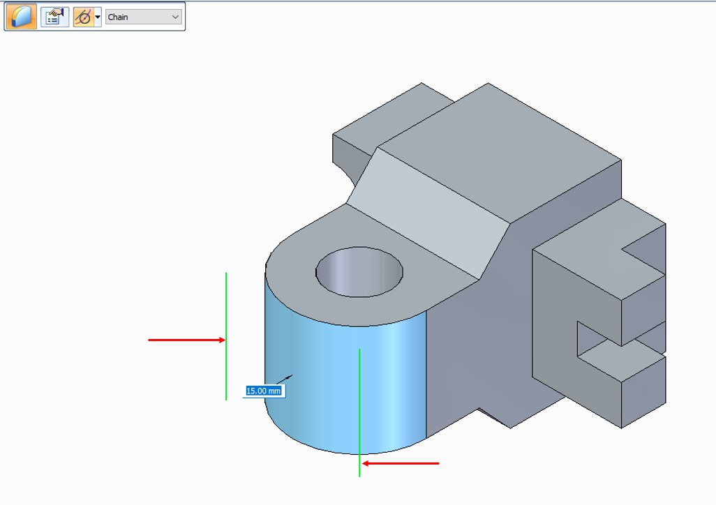
Step – 24:
Apply a 15 mm radius round on these two edges. Then Right-click to finish the Round feature.
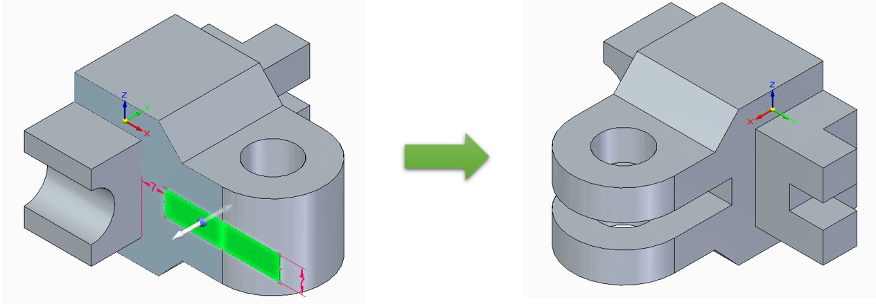
Step – 25:
Use Rectangle by the centre and draw on this side face.
Step – 26:
Select the full profile and create a through cut.
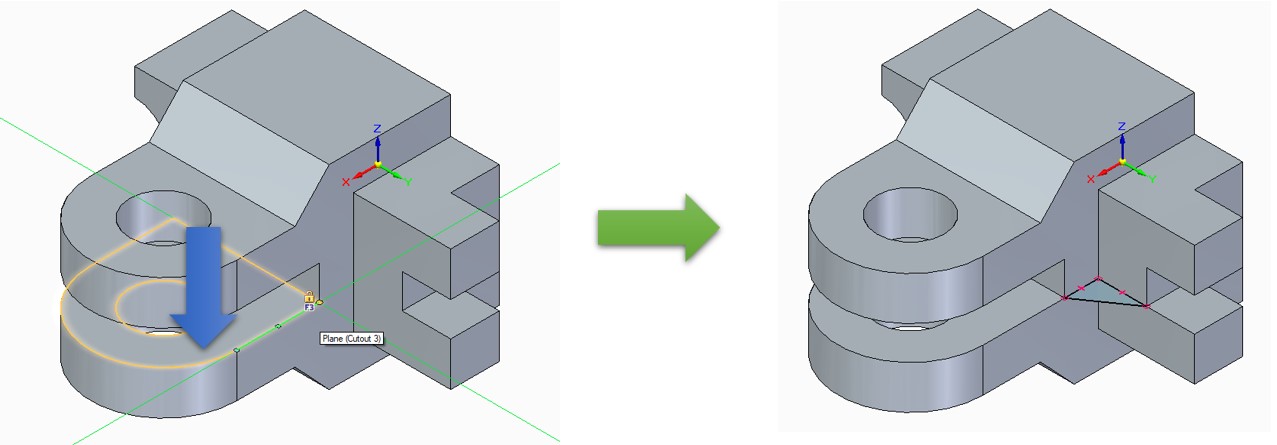
Step – 27:
Let’s create a triangle on a marked face using the line command. Need to just connect three corners to make fully constraint.
Step – 28:
Select this profile and just extrude up to the next upside corner. As shown in the image. No need to apply dimension. Just locate the top point to end the extrusion.
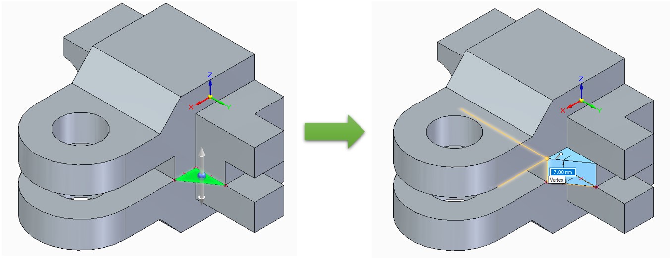
Finally, your part is ready now.
In this exercise we have learned about the sketch, a mirror in the sketch, a project sketch, extrude, cut, fillet, and synchronous edits. This exercise – 5 in synchronous mode can help you improve your part modelling efficiency. And to watch the CAD modeling practice click the below video. Also, please subscribe to us on YoutTube and Instagram for the latest updates. Your likes, comments and subscribes encourage us to do more better things for you.
Solid Edge Tutorial: Part Modeling Step by Step in Video