Page Contents
Solid Edge Tutorial: Synchronous Mode
Solid Edge is one of the best CAD modeling software. This CAD tool is a more user-friendly solution for engineers. This application is most suitable for Mechanical, Electrical Design, Simulation, Manufacturing, Technical publications, data management, etc. To better understanding this we have provided a Solid Edge Tutorial exercise.
Solid Edge is a package of affordable and, easy to use software tools that facilitate all aspects of product development processes. Solid Edge combines the speed and simplicity of direct modeling with the flexibility and control of the parametric design. This is possible with synchronous technology.
This post will give you step by step instructions on how to do a sketch, extrude, cut, fillet, chamfer and synchronous edits. Also, you can watch videos for the same exercise on youtube.

In this post also, we will learn How to Do Part modeling in the SYNCHRONOUS mode of Solid Edge.
Now, you have some doubts, what is the SYNCHRONOUS mode?
Synchronous mode… Why?
What is the difference between ordered mode and synchronous mode?
I hope, This post will clear all doubts.
What is SYNCHRONOUS mode?
Synchronous makes model, It doesn’t care how to do it? It believes in just move the parts and features. In short, you can make a part, but there is no history. So you can modify but can not change in history or hierarchy. But applying small changes will help a lot. You can pull and push any face of the part.
Why is SYNCHRONOUS mode?
Synchronous mode allows you to easily modify the part multiple times without entering in the sketch or history. It makes modeling more easier and faster. It combines the speed and simplicity of direct modeling with the flexibility and control of the parametric design.
Solid Edge synchronous technology helps you to immediately create a new concept design, easily changes and make simultaneous updates to multiple parts within the assembly.
What is the difference between the SYNCHRONOUS and ORDERED mode?
Ordered mode is the history-based way of modeling. In the ordered mode it is possible to go back and modify. It is very sturdy, but for frequent changes, it will be difficult.
Synchronous mode is very useful to create a part rapidly. And possible to modify it quickly without entering in the sketch. This mode provides more flexibility and power. But it requires more practice than the ordered mode.
Solid Edge Tutorial: Part Modeling Exercise –
In this exercise, we will make sketches and protrude them. Then also apply chamfers and cuts. So, in this tutorial, we will learn the extrude, cut, chamfer and hole commands. So as per the above image, let us start this part modelling. Please follow the instructions step by step.
Solid Edge Tutorial Step – 1
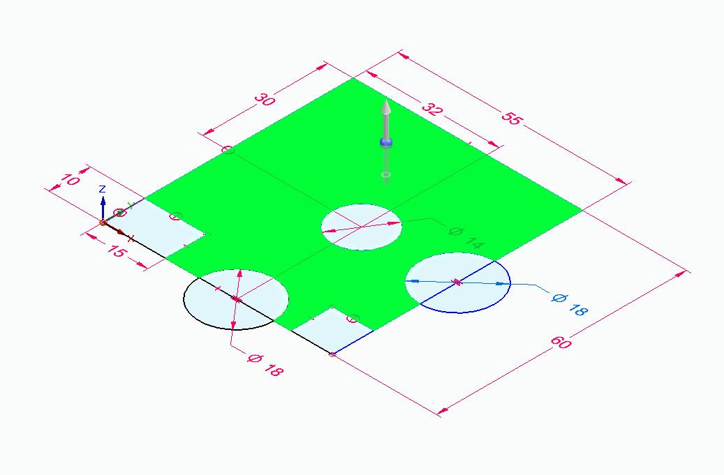
First, we need to create a sketch on the XY plane… hover the cursor on the XY plane… here F3 and lock sign pops up. This means you can lock this plane by pressing the F3 button. Then you sketch any view angle it will draw on the XY plane. Same for other planes as well. These things make sketching better. Please comment on this feature. Select rectangle by 2 points, start the first pint from origin to +X and +Y direction for the second point. So you will get the same viewing angle as in the drawing.
Now select Circle by centre points. Draw two semi-circles and one circle as per drawing, and apply dimensions to make it fully constraints. Then using the line command create two corners’ cutouts on both corners. Now, you have a sketch profile as shown below the image. Right-click on the common area and pull the arrow in Z-direction (on the top side) up to 15 mm height. Now, the base is ready.

Solid Edge Tutorial Step – 2
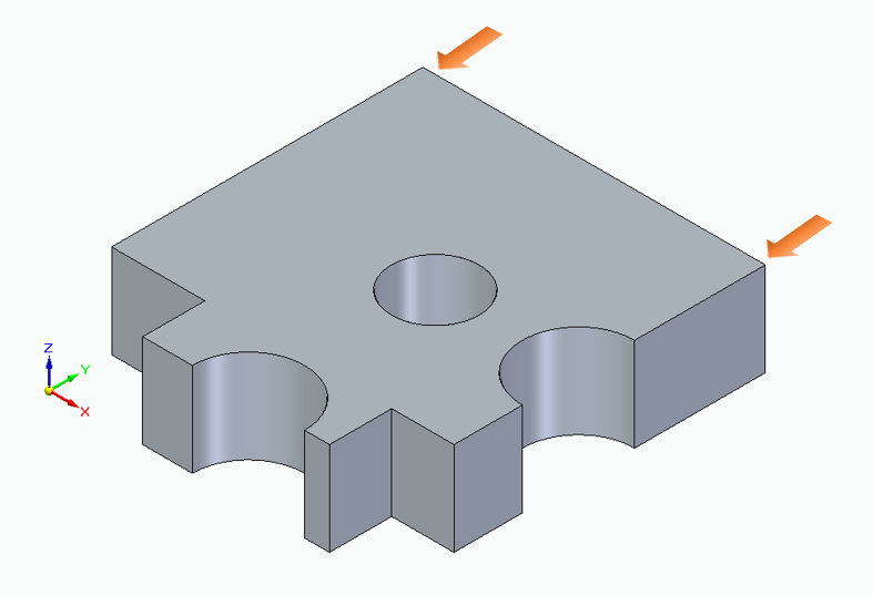
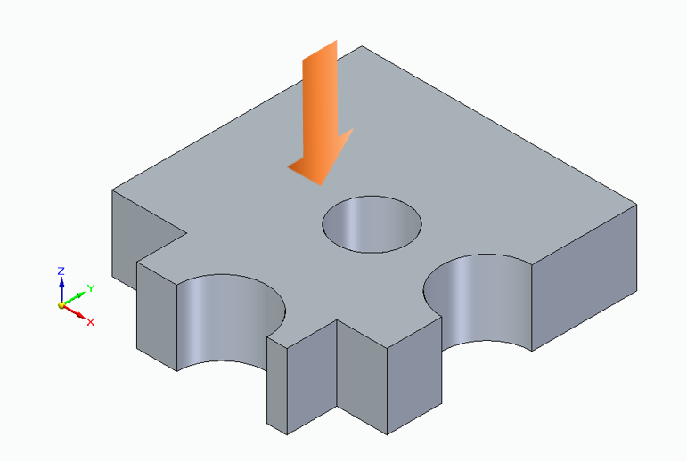
Apply chamfers on these two corners. Select Chamfer Unequal setbacks, Select two setbacks from the selection menu. Then select the first face then corner edge. And apply the dimension of setback 1 as 15 mm and setback 2 as 10 mm. And apply at both corners.

Solid Edge Tutorial Step – 3
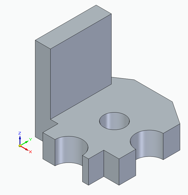
Now, create a rectangular on this plane size is 40 x 10 mm. Start it from the corner and pull up to 40 mm length and 10 mm width. As shown below image. The pull this profile in Z- direction up to 40 mm.

Solid Edge Tutorial Step – 4
Then…

Solid Edge Tutorial Step – 5
Now Hover the mouse cursor on this marked plane and lock it by pressing the F3 key. Create a sketch as shown in the next image. And protrude it up to the next face.

Solid Edge Tutorial Step – 6
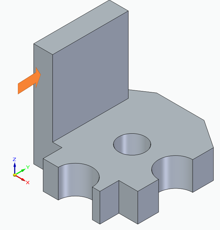
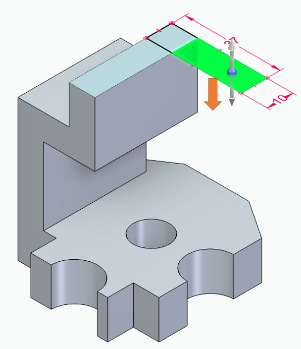
Now, draw a rectangular on this marked plane. Using locking the plane starts a rectangle from the plane’s corner. The length of this rectangle will be 37.5 mm and the width will be 10 mm. Please see the below image. Then extrude downside to the plane or 25 mm depth.

Solid Edge Tutorial Step – 7
Now, apply fillet on shown corners. The fillet radius is 12.5 mm.

Solid Edge Tutorial Step – 8
Now draw a circle on the shown plane, apply diameter as 12 mm of this circle and this should be concentric with both fillets. Now your part is ready. With all required dimensions. To get the PDF of this drawing please download it from the Downloads section. Also, you can click here to get redirect to the download section.

In this exercise we have learned about sketching, extrude, cut, chamfer and fillet commands for synchronous mode. The first time this part modeling takes 15-20 minutes for beginners. But after practising this time will be less than 10 minutes. So, for more efficient part modeling practice requires as well. And for more practices in solid edge using different – different features please stay tuned. And to watch the CAD modeling practice click below video. Also, Please subscribe to us on YoutTube and Instagram for the latest updates. Your likes, comments and subscribes encourages us to do more better things for you.