In engineering language, a cutting tool cuts or removes other material by applying force. Tools used in daily life like knives, chisels, scissors, etc. come under the category of cutting tools. A single-point cutting tool cuts a chip or material from a point or edge on a shank. Cutting tools are used in industries for creating the required shape of the product by facing, turning, shaping, drilling, boring, and many other operations. Lathe and shaper machines have single-point cutting tools in most of the operations. In industries, the most common examples of single-point cutting tools are turning, boring, shaping, planning, and slotting tools.

The objective of this post is to know about tool angles like clearance angle, rake angle, relief angle and various other geometry of cutting tools. Let’s, discuss single-point cutting tool geometry, various angles, nomenclature, signature, and material.
Page Contents
Single Point Cutting Tool Geometry and Nomenclature:
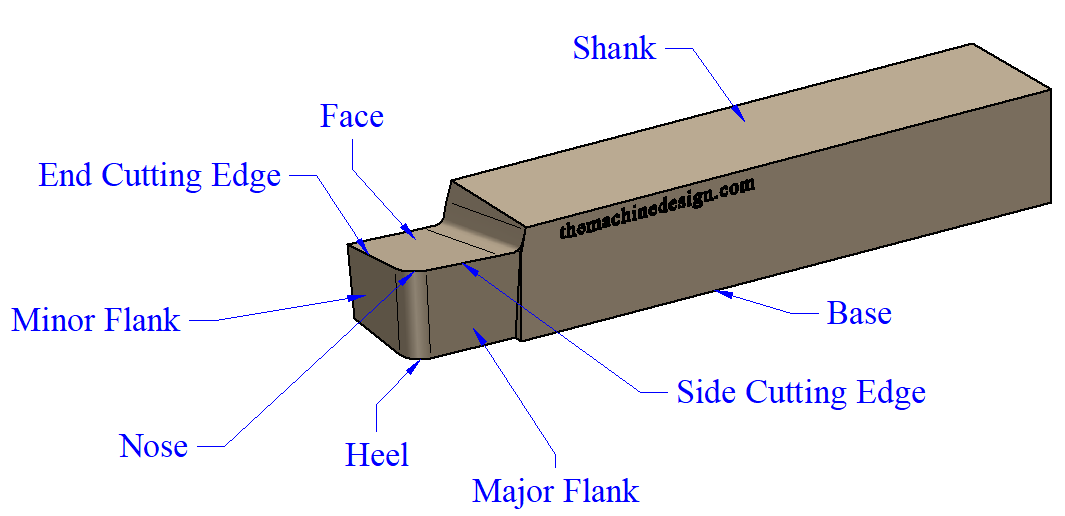
By means of a cutting tool, nomenclature is the systematic naming of various parts and angles of the cutting tool. The above image shows the complete nomenclature of a single-point cutting tool. These are shank, base, face, flank, heel, nose, back rake angle, side rake angle, side clearance, wide cutting edge, end cutting edge, and lip angle.
1. Shank:
Shank is the main body of the cutting tool, which is grabbed or supported by the tool holder on the machine. It is the largest and most rigid portion of the tool in terms of volume. It provides stability to the whole tool during machining operations.
The shank is designed with specific shapes and dimensions. So it can be configured with a specified tool holder. A proper tool design provides better alignment and clamping during machining.
2. Face –
The face is the surface of the tool where chips slide up and outward side, during the machining process.
3. Base –
The bottom surface of the tool is known as the base, on which the tool stands.
4. Nose or Cutting Point –
A point where side and End cutting edges are meets in front of the tool. It is also known as the Cutting Point of the tool. And Nose radius is the radius of the nose that helps to achieve better surface finishing as well as increases tool life.
5. Heel –
A line of intersection of flank and base surfaces is known as the Heel of a single-point cutting tool.
6. Flank–
Cutting tools have two flank surfaces, i.e; Major Flank and Minor Flank. The major flank is a vertical surface adjacent to the side cutting edge. And Minor flank is a vertical surface adjacent to the end cutting edge. But, both surfaces are not actually vertical, they slightly inclined towards the base. Cutting Face is another name for Flank.
Also Read:
- Top Most Expensive Materials in the World
- Working Principle of a Lathe Machine.
- 3 Kinds of Toggle Latches and their Different Uses
7. Cutting Edge –
Edges used to remove material during the machining process are called cutting edges. Faces and cutting surfaces make cutting edges. Single-point cutting tools have two cutting edges: the side cutting edge and the end cutting edge.
#. Side Cutting Edge – Edge or line made by face and minor flank or minor cutting surface.
#. End Cutting Edge – As like side cutting edge, end cutting edge is made by face and major flank or major cutting surface.
Single Point Cutting Tool Angles:
1. Rake Angle –
As you can see in the below image there are two Rake Angles from the side view of the tool. What are the two Rake Angles, let’s discuss.

#. Back Rake Angle –
The back rake angle of a single-point cutting tool is the angle between the face of the tool and the horizontal line which is parallel with the baseline of the tool. A back rake angle is useful in removing the chip away from the workpiece during the machining process. And also provides easiness in the machining process. If the slope of the face is downward toward the nose, known as Negative Back Rake Angle. That makes the blunt cutting edge of the tool. But increases the strength of the edge. It will increase the required power and cutting forces, and also increase the friction between tool and workpiece. But may help to improve the surface finishing of the product.
And If the slope faces is upward toward, known as Positive Back Rake Angle. Generally, a positive rake angle makes tools sharper. So, this reduces the required power and cutting forces during machining. But also reduces tool strength. And it can help to avoid the formation of a built-up edge.
If the slope is parallel with baseline, known as Neutral or Zero Rake Angle. It is easy to manufacture and re-sharpen. It requires a lesser power requirement and cutting force than a negative rake angle.
#. Side Rake Angle –
Side Rake Angle is an angled face and perpendicular line to the shank. As same as the side rake angle, the back rake angle is also helpful in removing the chip during the machining process. It provides clearance between the side flank and workpiece to prevent rubbing.

Also Read:
2. Relief Angle –
The meaning of relief is clearance. So, the relief angle having another name is Clearance Angle.
#. End Relief Angle – End relief angle is defined as the angle between a minor flank or minor cutting face and a perpendicular line to the base that makes the right angle with a flank. Therefore, it avoids rubbing the workpiece against the tool in a lateral direction.
#. Side Relief Angle – Side relief angle is defined as the angle between the Major flank or major cutting face and perpendicular plane to the base that makes a right angle with the side. It also avoids rubbing with the workpiece against the same as End relief angle but in a longitudinal direction.
3. Cutting Edge Angle –
Side Cutting Edge angle is defined as an angle between the side cutting edge and parallel line to the shank. In another name also called Lead Angle. And End Cutting angle is the angle between the end cutting edge and perpendicular line to the shank.

Conclusion:
Understanding the geometry and nomenclature of a single-point cutting tol is essential for cutting operations in lathe machines. Proper selection of rake angles, relief angles, and mose radius enhances tool life, reduces cutting forces, and improves surface finish. Engineers and machinists must consider these parameters to achieve precision machining, reduce tool wear, and enhance productivity.
Would you like me to add a diagram or any modifications?
FAQ’s:
[sp_easyaccordion id=”873″]


Which area is it used in wood ,plastic, metal,etc